2017-12-22, 04:00
This is a two-part question:

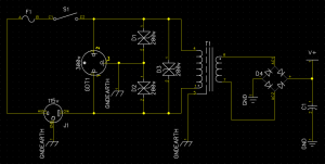
My thought process was that I just want the fuse to open and the whole thing to become inactive if anything goes out of spec, so during an overvoltage, I basically just want to short-circuit and blow the fuse. The rule of thumb that I have heard is that your device should be able to tolerate during normal operation anywhere between 100-140 volts from a 115v nominal mains supply. This means a peak AC voltage of ~198, hence the 200v TVS diodes. The clamping voltage of common 200v TVS diodes(http://www.kynix.com/Product/Cate/109.html) seems to be in the 320-330v range, so a 300v gas discharge tube was chosen to take up the larger surges a little bit before the diodes reach their limit. Anything more than the GDT can handle would probably just arc across the component leads and trip the mains circuit breaker or blow the power supply's fuse instantaneously, right?
Is this enough? Should I also fuse the mains neutral and use a lower voltage TVS diode for D2 in order to open the circuit in the case of reversed hot and neutral? It seems like it might be over doing it to try to protect against grossly incorrect mains wiring like that. Also, now I'm starting to ask myself if it isn't even more dangerous to risk opening the neutral side of the circuit before the hot side fuse blows...
- Why do so many projects that I see are using basic linear transformer power supplies (i.e., mains->transformer->rectifier->regulator) but not have any kind of input protection beyond a fuse? Is a fuse really going to help prevent damage to the circuit? Are they assuming that it's going to be plugged into a surge protector, so it doesn't need to worry about excessive input voltage?
- If it is a good idea to include more protection in a simple power supply, is a simple crowbar-type arrangement like this appropriate?
My thought process was that I just want the fuse to open and the whole thing to become inactive if anything goes out of spec, so during an overvoltage, I basically just want to short-circuit and blow the fuse. The rule of thumb that I have heard is that your device should be able to tolerate during normal operation anywhere between 100-140 volts from a 115v nominal mains supply. This means a peak AC voltage of ~198, hence the 200v TVS diodes. The clamping voltage of common 200v TVS diodes(http://www.kynix.com/Product/Cate/109.html) seems to be in the 320-330v range, so a 300v gas discharge tube was chosen to take up the larger surges a little bit before the diodes reach their limit. Anything more than the GDT can handle would probably just arc across the component leads and trip the mains circuit breaker or blow the power supply's fuse instantaneously, right?
Is this enough? Should I also fuse the mains neutral and use a lower voltage TVS diode for D2 in order to open the circuit in the case of reversed hot and neutral? It seems like it might be over doing it to try to protect against grossly incorrect mains wiring like that. Also, now I'm starting to ask myself if it isn't even more dangerous to risk opening the neutral side of the circuit before the hot side fuse blows...


