New Station Aerials and Noise Chasing
#1
The tale of my new blue station, roughly set up for testing, improving reception and reducing noise before installing.

Only H-field at the moment as the E-Field is far too noisy placed inside the house. H-field aerials are 3 x 38 cm 20 turn (square) loops wound with 7 x 0.5 mm dia stranded mains conduit wire, approx 1.3 mm^2 cross sectional area. The three loops are currently coincident and arranged at 90 degrees to each other. Why three? Why not the system can handle three and I had enough wire, wood and hooks to make three. Also 20 turn loops don't need transformers and I don't have suitable toroids to make transformers.

The stranded wire is just too big to fit into the terminal block on the H-field pre-amp board. So I used boot lace ferrules with the wire cores only half way down before crimping, leaving half the ferrule to be crimped small enough to fit the terminals.
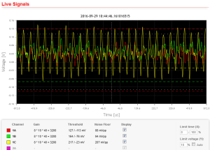
    Initial power up and exploration of the controller software showed horrendous noise. Traced to a poor USB power supply. I noticed while investigating this that channel 1C is most susceptible to showing noise and there where two ways it showed in the plots. One is a big signal on 1C with lower levels on 1B and 1A.
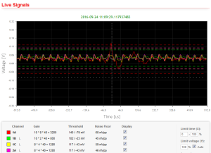
    Or a characteristic "sine wave with a kink". Fortunately I have a number of USB power supplies and one worked without interacting with the main board producing noise. Works so well you can't tell if the system is running from the USB power supply or 4 x 1.2 V NiMH batteries.
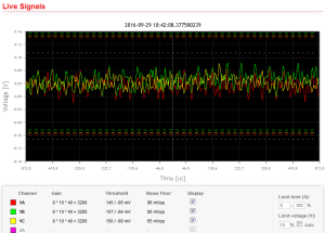
    So having got rid of the PSU noise I was left with either system noise or what was being picked up by the loops. Notice that there is a regular fairly fast signal in there, working out the period showed it to be 60 kHz, it also showed as a spike in the online frequency analyser plots. MSF, a time standard transmitter, located at Anthorn about 55 km away uses 60 kHz... Filter chips purchased and installed. Eye sight just about up to it and cut off frequency set to 50 KHz, bye bye MSF.
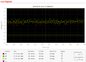
    No MSF but there is still something there that isn't random noise. Note that it's frequently in phase on 1A and 1B and out of phase on 1C. Doing the maths on the period shows this to be around 20 kHz. Along with Anthorn there is Skelton (about 30 km away). Both of these stations are believed to use frequencies around 20 kHz for communications with submerged submarines. This is effectively an "in band" signal so I guess I'm going to have to live with it and try an null it out on at least two of the loops by careful positioning of them.
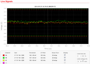
    Finally for comparison this is what I get with the loop RJ45 unplugged from the main board. Notice there is no regular signal in phase across the channels and more higher frequency elements. Apart from the second plot all these plots are with the system in manual mode and no change to the plot scales.

Reception doesn't appear to be much of a problem, the system is picking up signals from Tunisia around 2,500 km away and being used for locating strikes in Southern France. This is with the loops leaning against an internal stud wall inside a building with 18" thick exterior stone walls. The loops will eventually end up in a loft. E-field might be more of a challenge to get it far enough away from the house.

--
Cheers
Dave.
Cheers
Dave.

Stations: 1627
Reply
#2
Further noise chasing and reduction.

My 38 cm 20 turn loops from 7 x 0.5 mm dia stranded copper wire have a sharp and very deep null. Careful alignment can reduce the the extremely strong MSF 60 kHz carrier from Anthorn into the noise floor. It's a bit sensitive though the slightest movement and MSF comes back above the floor. I also found that the 20 kHz signal also comes from Anthorn, so for one loop both of those are sorted.

To aim the null of the loop accurately at Anthorn I connected an SSB communications receiver to one of the amplifier monitor ports. This receiver isn't supposed to go as low as 60 kHz but it does, it even goes down to 20 kHz but is beginning to get rather deaf by then. Using SSB makes the aiming dead easy just carefully rotate the loop until the whistle disappears.

Another "aiming aid" that is probably easier for most people to obtain is a spectrum analyser app for their smart device. I have Android and used Advanced Spectrum Analyzer PRO from Vuche Labs. Connect the smart devices mic in to one of the monitor ports. The mic in is probably on the second ring of the Tip, Ring, Ring, Sleeve 3.5 mm plug of a smart device headphone set with microphone. There will be a small voltage on that second ring to power the headsets electret microphone. A blocking capacitor might be wise if this connection is likely to be used for anything else. The Blue amplifier monitor ports are buffered and have a capacitor so aren't worried by this low voltage/current supply.

This app, and all other similar ones, are limited by the smart devices hardware to the audio band but this one will go up to 24 kHz. This showed me that the "20 kHz" carrier is actually 19.6 kHz and is 35 db above the noise on the loop looking at Anthorn. With the LP filter set to 16 kHz it's reduced to 10 dB above the noise. That's some sharp filter! It's not quite as easy to get the aim spot on but you can get pretty close.

The app also showed a smaller carrier around 16.4 kHz, that's not the frequency I was expecting from Skelton and anyway the bearing is wrong. Further research into the source of that carrier required. Skelton seems very quiet and is 26 degrees away from Anthorn so should be easy to tell apart.

The LP filters work very well, see above. For the loop looking at Anthorn I'll probably set the filter to 16 kHz to severely reduce the 19.6 kHz carrier. The other two set at 54 kHz to remove any residual 60 kHz signal but maintain as much bandwidth as possible to keep the rise time fast. On the loop with its null aimed at Anthorn I may try turning the filter off and see what Auto makes of that. With the 16/54 settings  Auto sets the gain of the three channels the same (4000) to get the target 50 mV noise floor for each channel. In theory that means the loops will pickup fairly evenly from all directions.

Awaiting arrival of a few bits to build a power supply filter to enable the use of a TP-Link TL-POE10R Power over Ethernet splitter and a box to mount everything in. Once those arrive the lot can be properly installed and I can think about where to put the E-field antenna.
Cheers
Dave.

Stations: 1627
Reply
#3
The filter attenuation is 57dB at 1.5 times f(CUTOFF),and 60dB at 2 times f(CUTOFF)
My guess is -20dB at 19,6KHz with a 16KHz filter

/Richo
Stations: 584, 585, 2017
Reply
#4
(2016-10-03, 17:45)RichoAnd Wrote: The filter attenuation is 57dB at 1.5 times f(CUTOFF),and 60dB at 2 times f(CUTOFF)
My guess is -20dB at 19,6KHz with a 16KHz filter

/Richo

60 dB/octave pretty damn steep. I'm a broadcast sound engineer so understand filters in dB/octave.

-20 is about what I saw bit difficult to get a really accurate reading as everything is bouncing around so a certain amount of "averaging by eye" was going on. Rolleyes

The 16.4 kHz carrier and bearing match with JXN, Noviken, Norway, 1000 miles away.

With there basically being no storms over Europe at the moment I'm pleased that I've got a low signal count, just over 100 for the last hour. That was in manual, switched to Auto and that has wound the gain up on a couple of channels giving them noise floors around 60 mV which I think is a bit high, the signal count has certainly gone up. These signals are very small only just hitting the default 120 mV threshold in auto, they don't quite make it in manual with the lower gain and noise floor nearer 50 mV.


Attached Files
.png   Man-Auto.png (Size: 7.01 KB / Downloads: 303)
Cheers
Dave.

Stations: 1627
Reply
#5
Installed ...

    The nice and compact 38 cm 20 turn loops attached to the ridge board by a home brew bearing so they can be easily rotated, locked off or removed.

    The bearing is a couple of saddle clips and 20 mm dia plastic electrical conduit and a length of 16 mm steel tube cross drilled each end. One cross drilling has pin that rests on the top of the conduit, the other takes a bolt to hold the antenna frame into the bearing. The conduit has a couple of slots cut at the lower end enabling a jubilee clip to tighten it onto the steel tube locking it in place. To stop the conduit rotating in the saddle clips it is glued to them.

    The controller mounted in a "Really Useful Box" A4 paper storage box, plenty of space and translucent so the LEDs can be seen. Couple of L brackets stop it sliding off the purlin. Power is via 802.3af PoE full details in the PoE recommendations for System Blue thread.

    Raw input, no LP filtering, equal gains.

Using a Frequency Analyser app on a tablet showed spot carriers on 16.4 Noviken, Norway; 18.3 Rosnay, France (moves about, also uses 21.7 and 22.6); 19.6 Anthorn, England; 22.1 Skelton, England. Noviken (1000 miles) and Rosnay (528 miles) are far enough away not to be a problem. Skelton (18 miles) must have been off a few days ago as you can't miss it now and it gives a nice beat pattern with Anthorn (38 miles).  Anthorn is tremendous signal but can be almost eliminated on one loop by aiming its null in that direction. Unfortunately Skelton then comes in pretty strong. On the plus side they are only 27 degrees apart and the noise floor figures from the controller's web interface was the best way to find a compromise position.

    Hard filtering, LP filtering set to give equal noise floors and thus equal gains.

 This loop is on Ch 1 and will have it's best pick up almost exactly N-S but only by chance it's alignment is dictated by Anthorn and Skelton... Of course the now E-W (Ch 2) loop gets fairly hefty doses of those stations. Setting the LP filter to around 17 kHz brings the noise floor down to that of the N-S loop at the expense of a lot of information above the cut-off frequency. The horizontal loop (Ch3) is less affected by Anthorn/Skelton but also doesn't pick up as many strikes as the two vertical loops.

    Soft filtering, LP filters set to remove as little as possible and have equal but high noise floors. The 54 kHz LP filter is to remove the 60 kHz MSF time standard transmission that also comes from Anthorn.

There is plenty of scope for more playing between "hard" LP filtering or "soft" LP filtering with or without equal gains. As can be seen the hard filtering does produce rather rounded and slow signals compared to the soft filtering.

Then there is the E field...
Cheers
Dave.

Stations: 1627
Reply
#6
Hi Dave,

Did you find a good source for the LTE filter ICs?

Looking at my signals, my main noise is at 20kHz and just over 60kHz.

I see RS have a good price, but are out of stock. I found someone on Amazon for about £8, after that they are over £12.

Robin
Reply
#7
I got my filter IC's from Farnell. Their website says they have 787 in stock @ £8.11 + VAT each (£9.73 inc). Go over £20 with an online order and you get free. UPS, next working day, delivery. Hope you have good eyesight they are flippin' tiny and not big enough for the "run a soldering along the pins" method. Fortunately they seem pretty robust, I missed soldering one complete edge of one of mine and it survived being powered.

That 20 kHz will almost certainly be Anthorn on 19.6. The LP filter is incredibly sharp set at around 16 kHz it'll pretty much remove even my huge 19.6 signal but at the expense of rise time and all the information above the cut-off frequency.

Spent the last couple of days re-engineering the aerials. Constructed another rotating mount, another single loop and a banana plug aerial patch panel. So I now have two vertical loops that can rotate independently. Ch1A has a loop with it's null aimed to get minimum signals from Anthorn/Skelton, meaning the lobes are more or less N/S. Ch1B has a loop set about 45 degrees clockwise from the first, so NW/SE. It still gets a fair amount of Anthorn/Skelton but less that being at 90 degrees. That's just how they landed, having drawn it out the second loop needs to go 135 deg clockwise to NE/SW. Ch1C has the horizontal loop.

Letting it run for a while like this to see how it performs. Alll HP filters in, only one LP filter set: 19 kHz in Ch1B.

PS. 4.5% cash back from Farnell via Quidco as well.
Cheers
Dave.

Stations: 1627
Reply
#8
Thanks Dave,

I saw Farnell had them so could have got them through work (we have an account). However, I found a seller on eBay who is about the same price, once the VAT is added, so ordered them from there.

Soldering them in shouldn't be a problem, I have hand soldered QFPs before.

I managed to get a spectrum plot of my interference, but posted it in another thread,
https://forum.blitzortung.org/showthread.php?tid=1995 Post #16.

The expected suspects are in there.

Robin
Reply


Forum Jump:


Users browsing this thread: 1 Guest(s)