Posts: 15
Threads: 1
Joined: 2017-03-14
2017-07-23, 08:52
(This post was last modified: 2017-07-23, 08:52 by Phil23.)
Hi All,
New Station installation completed a few hours ago & looking forward to feedback.
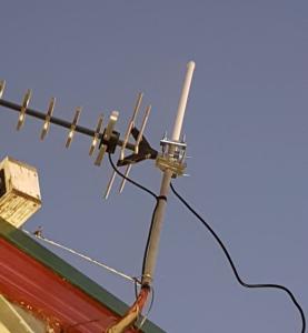
E-Field went in yesterday, about 150mm from memory.
First attempt at making a H-Field was completed a couple of hours ago.
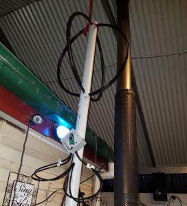
To get started I make a 4 turn Moebius Loop with RG6 Coax.
It's just hanging in the outdoor area ATM & plan to re-site everything later in the week.
Right now the GPS is shaded by a double iron roof.
Don't mind the idea of building another, better H-Field, but at least it's going now.
Any advice will be greatly appreciated.
Thanks
Phil.


Posts: 629
Threads: 73
Joined: 2012-08-15
Hello,
What is your station id?
You should install the H-field pre-amp closer to the loop.
The cables should be a little shorter.
Posts: 15
Threads: 1
Joined: 2017-03-14
Posts: 178
Threads: 22
Joined: 2014-01-18
2017-07-23, 11:31
(This post was last modified: 2017-07-23, 11:32 by kriu.)
(2017-07-23, 11:10)Phil23 Wrote: Station ID is 1928.
Hi Phil!
Is the loop antenna near the metal pipe? - is it a chimney?
If so, I suggest move a little away from this metal pipe.
I also suggest to attach a coaxial wire from the E-field antenna to the mast.
Good luck during system configuration - this is not a simple matter.
Posts: 15
Threads: 1
Joined: 2017-03-14
(2017-07-23, 11:31)kriu Wrote: Is the loop antenna near the metal pipe? - is it a chimney?
Yes, a heater flue. Not it's final location yet, need advice on that.
Also needs the Coax to the Amp tidied up & shortened.
I should maybe have mounted the junction box higher, it's currently 200mm below the loops.
Quote:I also suggest to attach a coaxial wire from the E-field antenna to the mast.
The TV antenna is not used, so it can be removed to help improved the E=field install,
Temporary initial install beating the dark last night...
Phil
Posts: 101
Threads: 7
Joined: 2016-09-17
Hi Phil,
the roof of corrugated iron will shield the loop antenna quite well, so when you place it on top of the roof or somewhere outside the H signals will go up considerably. The E signal appears to have a quite high noise of higher frequencies; maybe a filter would help. If you can find the source of this noise and remove it, it would be better but that may be hard to achieve.
Posts: 15
Threads: 1
Joined: 2017-03-14
(2017-07-23, 12:51)pasense Wrote: The E signal appears to have a quite high noise of higher frequencies; maybe a filter would help. If you can find the source of this noise and remove it, it would be better but that may be hard to achieve.
When you say High Frequencies, around which bands?
I have quite a few 433MHz transmitters monitoring control devices, all on 433.4MHz. They are all in default config of 100mW (20dBm).
I may well be able to lower their transmit power.
A few other 433's I can't reconfig. Also the Davis Pro2 is in line of site from the E-field about 10m away.
Wifi access points are fairly dense in my area also, including 4 in my residence.
Would like to understand a bit more about reading the noise figures so they can help me when I correctly site it.
Phil
Posts: 101
Threads: 7
Joined: 2016-09-17
Hi Phil,
"high frequency" is here relative to the frequency range of the lightning signals, and that's up to something like 30 kHz (or 30 kilocycles/sec), not anything like in the MHz range.... Just a bit above audible range. But in the signal plot of your lightning list I can see a quite regular (almost periodic) signal in the E channel and a broad noise in the frequency range above 30 kHz. Since it is always there I think there is some continously running noise source close by, but what is is I can't say. Could be a malfuctioning power supply in your house or one of a street lamp....
The noise signal does not appear in the H channels.
Posts: 15
Threads: 1
Joined: 2017-03-14
(2017-07-23, 12:51)pasense Wrote: The E signal appears to have a quite high noise of higher frequencies.
If you can find the source of this noise and remove it, it would be better but that may be hard to achieve. Found it. Around 30+kHz was coming from the Motorola 1 Amp power supply I was using.
Need to find a suitable replacement.
What do others think of using a more basic Linear supply.
IE older transformer type plug pack with something like a 7805 instead of a switch mode charger.
Phil.
Posts: 519
Threads: 18
Joined: 2016-06-09
Nothing wrong with a linear power supply and 7805. The lack of noise is a positive advantage. Lower effciency is the draw back but what is a couple of Watts?
Cheers
Dave.
Stations: 1627
Posts: 177
Threads: 9
Joined: 2013-12-14
(2017-07-27, 00:39)allsorts Wrote: Nothing wrong with a linear power supply and 7805. The lack of noise is a positive advantage. Lower effciency is the draw back but what is a couple of Watts?
The only problem is 7805 regulators normally only handle up to 1A and even then need a heat sink, there are other similar ones that have higher current ratings (I can't recalls he type numbers off the top of my head), why not just add a decent LC filter network, that is what I have done and it is as quiet as you could wish.
Ben.
RED Station: 878, Flightradar24: F-EGLF1, Open Glider Network: Aldersht2, PlanePlotter: M7.
Stations: 878
Posts: 519
Threads: 18
Joined: 2016-06-09
1 A is ample for a Blitzortung controller, if I remember correctly a controller draws 400 to 500 mA. Disipation in a 7805 is dependant on the voltage drop across it and the curent flowing through it. Minimum supply voltage is 7 V so it's dropping 2 V @ 0.5 A = 1 W dissipation, don't think that would need a heatsink. Feed it 12 V the disipation rises to 3.5 W, that probably will...
A post supply filter stops the noise getting to the controller via the power lines but doesn't stop the noise being radiated from the PSU itself or other wires connected to it. I'll admit I have post supply filter but I use PoE so don't (easily) have the option of a linear supply.
Cheers
Dave.
Stations: 1627
Posts: 177
Threads: 9
Joined: 2013-12-14
(2017-07-27, 22:26)allsorts Wrote: 1 A is ample for a Blitzortung controller, if I remember correctly a controller draws 400 to 500 mA. Disipation in a 7805 is dependant on the voltage drop across it and the curent flowing through it. Minimum supply voltage is 7 V so it's dropping 2 V @ 0.5 A = 1 W dissipation, don't think that would need a heatsink. Feed it 12 V the disipation rises to 3.5 W, that probably will...
A post supply filter stops the noise getting to the controller via the power lines but doesn't stop the noise being radiated from the PSU itself or other wires connected to it. I'll admit I have post supply filter but I use PoE so don't (easily) have the option of a linear supply.
Yes, you are correct, I was thinking more along the lines of the Raspberry Pi projects I have that need 2-3A, a 7805 should be fine for Blitzortung, I don't worry too much about the PSU radiating noise as it is only one if around 20 in the same room and I don't plan on changing everything to linear supplies.
RED Station: 878, Flightradar24: F-EGLF1, Open Glider Network: Aldersht2, PlanePlotter: M7.
Stations: 878
Posts: 519
Threads: 18
Joined: 2016-06-09
The only Raspberry Pi project I have that got me searching for a PSU that could supply a real 4 A is the media player. The Pi doesn't use it, it's spinning up the 2 T byte USB HDD.
Wandered about the house the other day placing the antenna of a SW receiver close to anything I thought might be radiating RF noise. Found three big offenders, two LED light bulbs and the electronic ballast for the aquarium lights. One of the light bulbs is Luminous brand from CostCo (UK), the other an unknown "brand" from the local hardware store. We have a mix of light bulbs in use, from tungstenm CFL, LED chip to LED filament. RF wise tungsten is silent, CFL noisy, LED chip significantly noisier, LED filament, quieter than CFL but not silent.
The many wall wart SMPSUs were on a par with CFLs, maybe a bit quieter. I know that some of them have noisy outputs from setting up my station. At some point I intend to invest in a multiple output CCTV power supply, these are a single box conatins a 12 V 10 A (or more) PSU and distribution for individually fused outputs. Need to check what everything actually lives off, if something wants a lower voltage I have some LM2956 based DC-DC convertors that I hope don't radiate too much.
Aquarium? Need to investigate that, it's double insulated so has no ground connection for starters.
Cheers
Dave.
Stations: 1627
Posts: 101
Threads: 7
Joined: 2016-09-17
The worst source of noise I have detected so far is an induction plate we use for cooking. It generates strong magnetic stray fields which have unfortunately a frequency exactly in the range we need to detect, so these signals cannot be filtered out. I will have to move the ferrite antenna as far away from the kitchen as I can.
Posts: 519
Threads: 18
Joined: 2016-06-09
Well I'm not surprised an induction hob is a noise source, after all it uses a powerful magnetci field to heat the pan... I will have to see what our single ring portable one shoves out. At least a induction hob is off far more than it is on, unlike light bulbs. B-)
Cheers
Dave.
Stations: 1627
Posts: 101
Threads: 7
Joined: 2016-09-17
Distant second in terms of (magnetic) noise is the aircon unit (the indoor part), but this problem will certainly also be solved when I move the antenna.
|


