Posts: 12
Threads: 4
Joined: 2017-05-05
2025-04-19, 23:28
(This post was last modified: 2025-04-20, 06:27 by DrFX.)
Hi,
I have a System Blue Basic, is there a way to extend the indicator emitters to a panel on an enclosure for the Blue Basic? The older designs had the LEDs at the front of the board. Now they are in the middle.
Has anyone extended the status or indicator emitters to the front panel by way of ribbon cable or otherwise for the his System Blue Basic?
I'm wondering if there is an existing kit for the indicators I could leverage, or if I would need some kind of ribbon cable to extend the functionality out to a front facing panel?
What do you all recommend?
Thank you,
Kindly.
Posts: 3
Threads: 2
Joined: 2025-04-08
It’s definitely possible! Many users have extended the LEDs on System Blue Basic using ribbon cables or jumper wires with external panel-mount LEDs. There's no official kit, but it's a common DIY mod. Just be mindful of current-limiting resistors and polarity. A small perf board or custom PCB can help keep things neat.
Posts: 12
Threads: 4
Joined: 2017-05-05
2025-05-09, 01:35
(This post was last modified: 2025-05-14, 09:51 by cutty.)
(2025-05-06, 07:27)WonderNomad Wrote: It’s definitely possible! Many users have extended the LEDs on System Blue Basic using ribbon cables or jumper wires with external panel-mount LEDs. There's no official kit, but it's a common DIY mod. Just be mindful of current-limiting resistors and polarity. A small perf board or custom PCB can help keep things neat.
Thank you! Would you be willing to show how you did your mod?
Posts: 1,935
Threads: 63
Joined: 2013-07-23
2025-05-14, 09:37
(This post was last modified: 2025-05-14, 21:37 by cutty.)
(2025-05-09, 01:35)DrFX Wrote: (2025-05-06, 07:27)WonderNomad Wrote: It’s definitely possible! Many users have extended the LEDs on System Blue Basic using ribbon cables or jumper wires with external panel-mount LEDs. There's no official kit, but it's a common DIY mod. Just be mindful of current-limiting resistors and polarity. A small perf board or custom PCB can help keep things neat.
Thank you! Would you be willing to show how you did your mod?
I question WonderNomad's response, which appears to be a possible pre-school AI response...
UPDATE: Important: depends on board version!
DRIES explains in next post.
I'm not sure it's actually feasible for many folks... I wouldn't fool with it, myself on a Mini/Basic... The Blue Mini doesn't appear to have the solder pads for external leds. Blue Max did, and many have installed the LEDs ... some came with the earlier kits.
I don't operate a mini/basic, all mine are Big Red & Blue Max systems...
Here's how it worked on the Full Blue:
I choose to stay in the generic mad scientist role... transparent Sasquatch Built primitive dust cover ... although the last one for 3020 on the right on The Blitz Wall below shows improvement over the first three... heh...
I can observe ALL the purty flashin' lites at a glance.
The 'Mad Scientist' mental illness vrs Blitzortung at Frankfort Weather.us --- :
![[Image: madscientist2thumb.jpg]](https://frankfortweather.us/blitzblitz/madscientist2thumb.jpg)
Click to open ABAP in your browser. (' ABigAssedPicture')... could take awhile. Tuff.
Posts: 650
Threads: 5
Joined: 2017-11-24
2025-05-14, 20:47
(This post was last modified: 2025-05-14, 20:50 by dupreezd.)
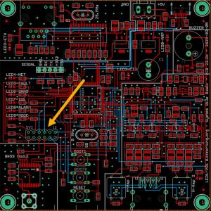
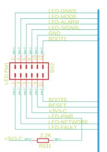
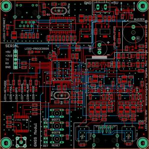
I had look at the Mini boards as posted by Egon. It looks like he did some modifications to the layout and added a header to connect external leds on the 22b boards.
I do not have a mini, but it looks like the spacing is such that you can solder a pin header in there and then use a ribbon connector to plug in. The other end can the be connected to Leds. Yes, I will not solder directly to the board, but use a header.
The header does provide both +3.3v with a load resister and gnd. See schematic.
I would use the lowest current draw led's I can get, as normally each led has it own load resister.
Dries
Posts: 1,935
Threads: 63
Joined: 2013-07-23
(2025-05-14, 20:47)dupreezd Wrote: I had look at the Mini boards as posted by Egon. It looks like he did some modifications to the layout and added a header to connect external leds on the 22b boards.
I do not have a mini, but it looks like the spacing is such that you can solder a pin header in there and then use a ribbon connector to plug in. The other end can the be connected to Leds. Yes, I will not solder directly to the board, but use a header.
The header does provide both +3.3v with a load resister and gnd. See schematic.
I would use the lowest current draw led's I can get, as normally each led has it own load resister.
Dries Well Done Dries! 
I THOUGHT I'd seen that somewhere ! 
I've got to go find it. It's not in my local 'collection'. Since my post may be relevant to a few boards (?) I'll leave it up for now.
Posts: 650
Threads: 5
Joined: 2017-11-24
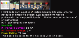
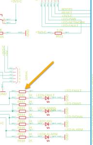
Digging deeper into the schematic, I do notice there is already provision made for a 1K load resistor per individual LED. I dont know if the board comes with the resistors pre-installed, but they are 0603 SMD's, so not to difficult to solder on if not already there.
It appear the 2.2k resistor is for the Power On led going to pin 5.
I would be very careful not to short pin 7 (+3V3-C) to ground.
Posts: 1,935
Threads: 63
Joined: 2013-07-23
2025-05-15, 01:43
(This post was last modified: 2025-05-15, 01:43 by cutty.)
(2025-05-14, 22:16)dupreezd Wrote: Digging deeper into the schematic, I do notice there is already provision made for a 1K load resistor per individual LED. I dont know if the board comes with the resistors pre-installed, but they are 0603 SMD's, so not to difficult to solder on if not already there.
It appear the 2.2k resistor is for the Power On led going to pin 5.
I would be very careful not to short pin 7 (+3V3-C) to ground.
I'm pretty sure those are the 'onboard' LEDs, installed. DrFx says they're 'in middle of board'... can't see 'em when in enclosure... wants to install panel mount... when I've more time maybe... gettin' old, Dries... 
Posts: 98
Threads: 18
Joined: 2017-11-10
Maybe working with glassfiber ...
Position one end just above a LED and it probably will show on the other end the LED light.
Making a tiny hole in the front panel and stick the other end of the glassfiber through the hole
Just an idea ;-)
Posts: 12
Threads: 4
Joined: 2017-05-05
2025-05-18, 02:12
(This post was last modified: 2025-05-18, 02:18 by DrFX.)
(2025-05-14, 22:16)dupreezd Wrote: Digging deeper into the schematic, I do notice there is already provision made for a 1K load resistor per individual LED. I dont know if the board comes with the resistors pre-installed, but they are 0603 SMD's, so not to difficult to solder on if not already there.
It appear the 2.2k resistor is for the Power On led going to pin 5.
I would be very careful not to short pin 7 (+3V3-C) to ground.
(2025-05-15, 01:43)cutty Wrote: (2025-05-14, 22:16)dupreezd Wrote: Digging deeper into the schematic, I do notice there is already provision made for a 1K load resistor per individual LED. I dont know if the board comes with the resistors pre-installed, but they are 0603 SMD's, so not to difficult to solder on if not already there.
It appear the 2.2k resistor is for the Power On led going to pin 5.
I would be very careful not to short pin 7 (+3V3-C) to ground.
I'm pretty sure those are the 'onboard' LEDs, installed. DrFx says they're 'in middle of board'... can't see 'em when in enclosure... wants to install panel mount... when I've more time maybe... gettin' old, Dries... 
I've attached two pictures in the links provided they are high resolution of the Blue Basic. Open the image if a separate tab and zoom in if you need to see more details.
![[Image: 02-Blitzortung-Blue-Basic-High-Resolution.jpg]](https://i.postimg.cc/XnQX8Jqc/02-Blitzortung-Blue-Basic-High-Resolution.jpg)
![[Image: 01-Blitzortung-Blue-Basic.jpg]](https://i.ibb.co/n868mHdt/01-Blitzortung-Blue-Basic.jpg)
![[Image: 03-Blitzortung-Blue-Basic-Close-of-Chips.jpg]](https://i.ibb.co/rR7LNV9g/03-Blitzortung-Blue-Basic-Close-of-Chips.jpg)
Posts: 1,935
Threads: 63
Joined: 2013-07-23
2025-05-18, 06:27
(This post was last modified: 2025-05-18, 06:49 by cutty.)
Seeing those images of controller 3410, a v22.2 board, which is what I was referring to originally, I see no header, and no designed provision for 'external' leds. I go back to my initial response, in this situation, " I'm not sure it's actually feasible for many folks... I wouldn't fool with it, myself on a Mini/Basic... The Blue Mini doesn't appear to have the solder pads for external leds." Remember Mini is designed to be as simple and low cost as possible. No bells, whistles, no e field, no auxiliary signal outputs or variable digital low pass filter options, even the switchable High Pass amplifier stages are removed, and additional gain (15?) added to preamplifier to compensate in this basic version. Sure, this one could be 'worked around', with background and skills, etc., but, for this production version, I think this is more in the tone of J.P. Morgan's response to maintaining a yacht: "If you have to ask the cost , you can't afford it".
Posts: 650
Threads: 5
Joined: 2017-11-24
2025-05-18, 11:21
(This post was last modified: 2025-05-18, 11:24 by dupreezd.)
Yes, I agree with Cutty, unfortunately this is Revision 1 of the Blue Mini with no provision made for extending the LED's to the front panel.
rwvdknoop suggestion can be implemented by using a 3D printed block with holes over each LED to hold a fiber optic that extends to the front panel. Hot glue it over the LED's to hold it in place.
Always keep in mind, what ever you decide to do, "What if I need to remove the board from the case?"
Posts: 60
Threads: 20
Joined: 2014-09-22
2025-06-27, 00:31
(This post was last modified: 2025-06-27, 00:33 by Geewizard.)
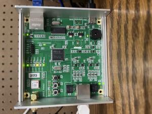
I just leave the top cover off of mine.
Posts: 2,178
Threads: 78
Joined: 2012-06-26
Posts: 60
Threads: 20
Joined: 2014-09-22
(2025-07-05, 15:30)Tobi Wrote: This option might be a solution too: https://forum.blitzortung.org/showthread...8#pid27198
I'm going to give this a try. Thanks Tobi.
Posts: 912
Threads: 55
Joined: 2012-06-26
Hello everyone,
I've designed a piggyback board for PCB 22.2b. It connects to the 12-pin header via a 12-pin female connector and can be inserted into the upper slot of the case. The 22.2c board has no other components besides the LEDs, buttons, and a female connector.
![[Image: piggyback.jpg]](https://www.limaps.org/Graphics/piggyback.jpg)
![[Image: Housing_2_front.jpg]](https://www.limaps.org/Graphics/Housing_2_front.jpg)
![[Image: Housing_2_back.jpg]](https://www.limaps.org/Graphics/Housing_2_back.jpg)
/Egon
Posts: 335
Threads: 11
Joined: 2014-07-21
nice and clean setup wit this new extra board and case.
Guess I'll have to invest one of these, got an early non B version 
Posts: 54
Threads: 5
Joined: 2025-06-28
I posted a make for the Blue Mini.
You just need some clear plastic to bring lights to the front.
https://forum.blitzortung.org/showthread.php?tid=4128
D
|


![[Image: madscientist2thumb.jpg]](https://frankfortweather.us/blitzblitz/madscientist2thumb.jpg)


![[Image: 02-Blitzortung-Blue-Basic-High-Resolution.jpg]](https://i.postimg.cc/XnQX8Jqc/02-Blitzortung-Blue-Basic-High-Resolution.jpg)
![[Image: 01-Blitzortung-Blue-Basic.jpg]](https://i.ibb.co/n868mHdt/01-Blitzortung-Blue-Basic.jpg)
![[Image: 03-Blitzortung-Blue-Basic-Close-of-Chips.jpg]](https://i.ibb.co/rR7LNV9g/03-Blitzortung-Blue-Basic-Close-of-Chips.jpg)
![[Image: piggyback.jpg]](https://www.limaps.org/Graphics/piggyback.jpg)
![[Image: Housing_2_front.jpg]](https://www.limaps.org/Graphics/Housing_2_front.jpg)
![[Image: Housing_2_back.jpg]](https://www.limaps.org/Graphics/Housing_2_back.jpg)
